A system for adjustment and maintenance of RFoG devices in PON network
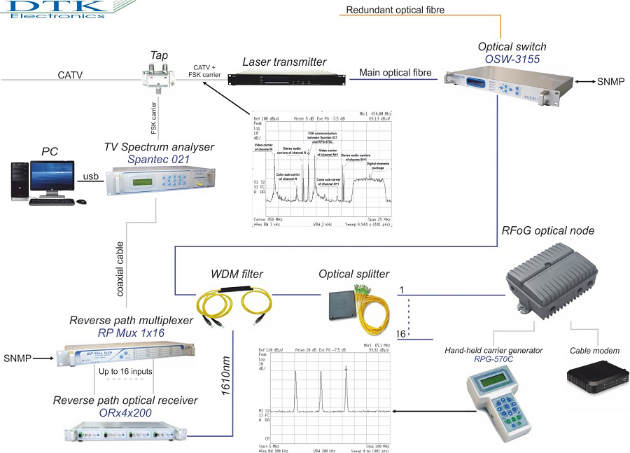
The system for adjustment and maintenance of return paths in PON network with RFoG nodes is built based on Headend standard equipment and additional units performing the measurement and monitoring functions. On the figure is shown a portion of Headend equipment necessary for configuring a complete system for adjustment and monitoring the return paths of a PON network with RFoG nodes.

Brief description of the devices and interconnections:
The spectrum analyzer Spantec-021 generates with its built it FSK modulator a carrier which has been added to the complex signal produced in Headend. This carrier serves for communication between Spantec-021 and the hand-held generator RPG-570C which is used for the adjustments. Then the complex signal has been fed to an optical transmitter where it’s been converted into optical signal with appropriate power.
If providing of uninterrupted optical signal is essential, a redundancy system is applied. It consist of optical switch OSW-3155 and two independent optical fibers carrying two signals. They are fed to the two inputs of OSW-3155 Signals’ powers are permanently measured and compared. Should the main signal drops or worsens, the optical switch automatically the redundant signal to the output. The switching time is approx. 8 ms.
The spectrum analyzer Spantec-021 used in the measuring system is connected over USB with a computer or server to transfer measuring data for visualization and processing.
To each output of the optical splitter is connected one RFoG node. Each node can handle up to 32 cable modems. As the outputs of the splitter in respect to return path act as inputs, it gathers 8 or 16 optical fibers coming from the nodes.
RFoG nodes’ laser diodes emit optical signal which, after gathering by the splitter, is separated by WDM filter and fed to one of the inputs of an optical receiver ORx 4x200.
For the purpose of adjustment and maintenance in the course of running the network, there must be possibility the return paths to be connected to one or more measurement instruments. This function is performed by the return path multiplexer RP Mux 1x16 which is capable to switch 16 inputs to 1 output and has frequency bandwidth 5 ÷ 200 MHz. If necessary to switch more than 16 return paths, two or more multiplexers could be cascaded. The multiplex ratio becomes accordingly 31:1, 46:1 etc.
Adjustment method:
Measurement instruments used for adjustment the network are spectrum analyzer Spantec-021 and hand-held return path generator RPG-570C. The two devices communicate to each other bidirectionally through the network by means of a FSK carrier.
The generator RPG-570C is connected to a remote point of the network. Its internal DDS (Digital Direct Synthesis) could be programmed to generate up to three different carriers in the range 5 ÷ 70 MHz with amplitude 70 ÷ 120 dBμV.
Whenever RPG-570C generates a carrier it’s been sent over the network and Spantec 021 measures its level as received in the Headend. Then it sends the information over the communication channel back to RPG-570C. Thus:
- On the display of RPG-570C is shown the RF level measured at the input of CMTS without built up errors. This allows the technician to perform accurate adjustment of network trunk.
- Test carriers appear and disappear consecutively and when their level exceeds appointed threshold, the RFoG node’s laser diode turns on. In this way is simulated operation of a cable modem in selected frequency range.
- Test carriers’ frequencies should be set at the beginning, middle and end of return path bandwidth. Thus could be obtained a best notion about operation of RFoG node in the whole return path range.
- A precise alignment of laser diode turn-on threshold (Burst-edge) is achieved.
Adjustment procedure:
- Setting the frequencies and RF levels on RPG-570C. At these levels the RFoG node’s laser diode turns on.
- Programming RFoG node’s gain so that Laser ON /OFF LEDs start flickering.
- Setting optical modulation index OMI [%] referring the diagram in RFoG node’s manual. The criteria for optimal OMI are the RF level at the input of relevant CMTS Upstream port, and C/N ratio.
If needed a signal could be applied at the point of connecting a cable modem. By achieving the same level at CMTS input could be determined the level at which the cable modem will operate.
Summary:
The system and methods described above help for fast and accurate adjustment and permanent monitoring of the optical network. CMTSs and RFoG nodes aligned using above described procedure, connect and operate at their optimal levels. This is of extreme importance for reducing faults down to minimum and thence for improving the quality of offered service.
« Back to all posts.


